Ham radio projects by SM7TKR. Henry 1KD-5 restoration. F1JRD 2m LDMOS Amplifier with MRFE6VP61K25H.
Search This Blog
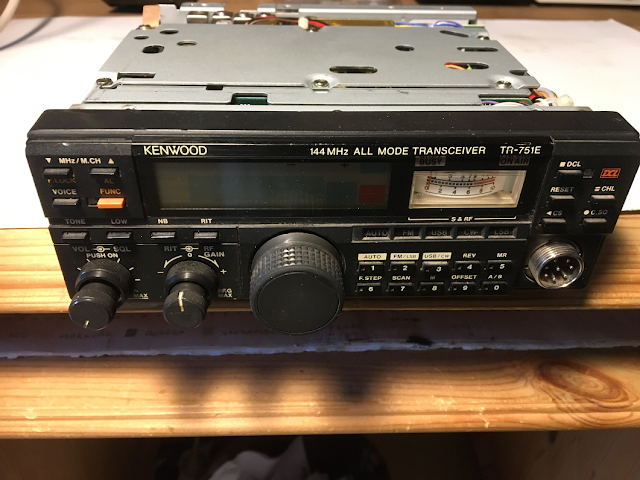
Saving the Kenwood TR-751/TR-851 transceiver from the electronic scrap yard
The very first VHF transceiver I bought when I got my HAM license was the
Kenwood TR-751E.
It was at the time in the early 90's one of the best
VHF transceivers on the market.
After a while the very well-known
potentiometer problem started to appear.
At the time there was still
spare parts to be found, today it is a different story.
I came
across two stations, one TR-751E and also a TR-851E for as I saw it, a very
reasonable price.
The low price was as I suspected due to the faulty
potentiometers, but that could easily be fixed, right?
NO...! I
Searched the Internet for several hours looking for spare parts and I ended
up with nothing.
The problem is to find a double potentiometer with the
shaft diameters and lengths that are used in
the TR-751/851 models.
There are two potentiometers that could fit with some modification.
RV50303522
for the Vol./Sql./Pwr.
RV20303523 for the RIT/RF Gain.
Unfortunately I could not find a
supplier who would ship to Sweden :(
On the other hand the previous
owner had done Vol/Sql replacement which would have been much harder to
repair.
So what to do? Could the faulty RIT potentiometer be
repaired or modified somehow?
I came up with an idea to reuse the
shafts and use standard trimmer potentiometers.
This is how I did it....
The radio was opened up and the front panel removed.
Circled in
the picture above you can see the two potentiometers. The one to the right
is the faulty
RIT/RF Gain potentiometer.
While I was at it, I also
replace one broken LCD lamp. It was a lot of work just to replace a lamp.
Potentiometer removed from front panel.

Dismantling the potentiometer I realized that it was beyond
repair.

I ordered two 10k potentiometers from my favourite electronics supplier.
Together
with the original shafts and a piece of an experimental board I had the
parts to build
a new functional double shaft potentiometer that would
fit inside my TR-751E.
The RF gain potentiometer soldered to the experimental board.

RF gain section completed with outer shaft mounted, and board cut to
fit inside the radio.
A drop of glue was added to keep things in place before assembling it
together with the RIT shaft.

Rit potentiometer mounted and aligned with the shaft.

The new potentiometer is soldered to the original board with wires
about 5cm long so that the board
could be stowed away to the side.

RIT/RF Gain potentiometer mounted in place. Nice fit!

Works well. Mission accomplished. Radio saved from the electronic scrap
yard!
And the radio sounded excellent! /Oskar
ReplyDeleteGood job!
ReplyDelete