Ham radio projects by SM7TKR. Henry 1KD-5 restoration. F1JRD 2m LDMOS Amplifier with MRFE6VP61K25H.
Search This Blog
144MHz 10 Element Long Yagi
We decided to replace the 10 element gamma fed 144MHz Yagi, with two vertically stacked
10 element Yagis.
The idea was to build one of Justin's, G0KSC OWL designs,
but unfortunately the aluminium material I had at home did not match any of his simulations.
So instead I had to make a new simulation using his 10 element OWL design as a starting point.
Using MMANA-GAL, this was my final simulation result.

I am excited to start building this antenna.
The antennas are going to be put up in an 18m high tower, vertically stacked 3.2m apart.
Further tweaking was done to maximize gain. Maybe I was overdoing things again....
In practice when building an antenna at home, it is very difficult, no matter how meticulous
you are, to make the antenna exactly as the one in the simulation.
Drilling holes, element lengths etc will vary in about 0.5mm or so, and the pattern will no longer
be the one that was done in the simulation.
Anyhow, the below plot shows the tweaked antennas.
The lower antenna is placed at 18m and the second stacked 3.2m apart.

Building the antennas
As mentioned earlier, to keep the cost as low as possible the simulation was done so I could use the aluminium material I already had at home.
A little more gain could probably be squeezed out using thicker elements for the radiators.
However, I think it will be Ok even if the antennas according to the simulation are very narrow banded. They probably will be within 1:1.15 400 kHz.
Element size and spacing

BOM List (One antenna)
- 6m 25x25x2mm Square aluminium tubes for the boom.
- 1m 20x20x2mm Square aluminium tubes to join the boom parts.
- 1.1m 10x1.5mm for the reflector element.
- 2m 8x1.5mm for the folded dipole.
- 8pcs of 1m 6.0mm aluminium rods.
- 20 clips, element holders.
- 20 6mm stainless steel screws and nuts.
- Connection box to connect coax to the dipole.

Reflector and director elements cut for the antennas

Booms with element holders put in place

All elements except for the T-match are mounted
The folded dipole
In the past I have always built my antennas with a gamma matched feed point.
It has always worked well for me in monoband single antenna configuration.
According to the information found on the internet the gamma feed point is nowadays
less used because of its asymmetric behaviour. I will use a folded dipole feed instead.
Picture showing RF Choke and folded dipole
connector box.
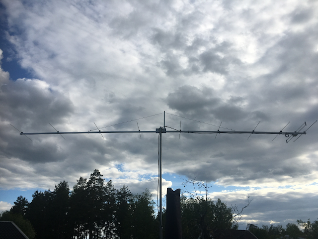
The finished 10 element Yagi put up for
test.
Two antennas finished and ready to be put up
at SK7IJ's contest site.
It was a lot of work and I am quite happy with the result.
I forgot to save the SWR plots from my nano-VNA for the blog, but for what I
can remember the
SWR-plot was very close to the one in MMANA-GAL simulation.
SWR-plot was very close to the one in MMANA-GAL simulation.
I will measure the antennas again when we have put them up in the tower at
our club QTH and post them here.
Until then 73's
Subscribe to:
Comments (Atom)


Looking good!
ReplyDeleteGoing to be fun to try them on SK7IJ.
//SM7VGQ
It would be great to see the folded dipole details. thanks
ReplyDelete